


All the Current Transformer Design Specifications You Need to Know
A current transformer is an electric device used to measure electric current flowing through a power system. Read on to know more about the design and design specifications of these devices.
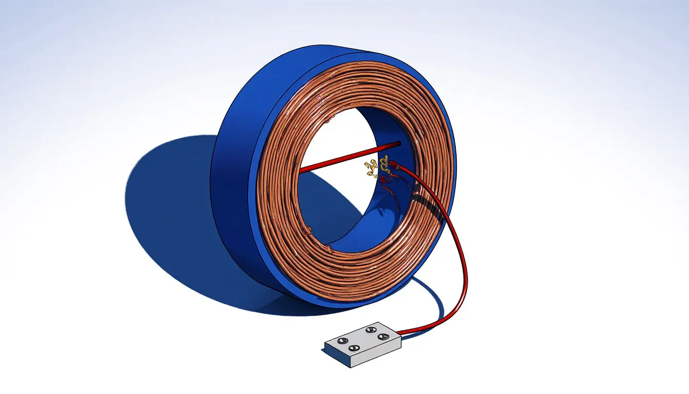
A transformer is a device that transmits electricity from one circuit to another through inductively coupled transformer coils. A current transformer is an integral part of electrical engineering, which when used with a potential transformer, is known as an instrument transformer. When the current in a circuit connected to a measuring instrument is extremely high, the current transformer generates a reduced current which is directly proportional to the circuit current, so that the circuit can operate with the measuring device with no risk of getting damaged. It not only minimizes the current, but also isolates the measuring instrument from the circuit, especially if the circuit is having very high voltages.
Current Transformer Design
Current transformers consist of primary and secondary winding, and a magnetic core. The alternating current flowing in the primary winding generates a magnetic field which induces current flow in the secondary winding. Their main objective is to have properly coupled primary and secondary circuits, so that the secondary current is proportional to the primary current. The most basic design comprises a length of wire wrapped around a silicon steel ring passed over the circuit being measured. The primary circuit consists of a single turn of a conductor, with a secondary circuit with many number of turns.
The primary winding is the most important part of the current transformer and with a heavy copper bar, it transmits current through the magnetic core. The secondary winding can be single ratio or multi-ratio; usually five taps are commonly considered for multi-ratio. The load should be of low resistance and the core’s design rating should be more than the voltage time integral area, else the core may enter into saturation mode at the end of each cycle, and will affect the transformer’s efficiency.
Design Specifications
Following are some design specifications that are necessary to be considered before designing a current transformer.
- Maximum current value, kind of measurement (rms, average, peak, etc.), type of waveform (sine wave, square wave, triangular, etc.), duty cycle, etc., are important specifications that should be considered.
- Evaluation of parameters, like number of primary turns, current ratio, secondary current value at specific primary current value.
- Value and type of the intended secondary load, i.e., whether it is resistive, inductive, or capacitive. Commonly resistors are used as a secondary load, whose value can be calculated after alternatively measuring the desired output voltage with respect to the primary current.
- Accuracy is another specification which is expressed as a maximum percentage or maximum absolute change over the complete primary current range. It comprises both, measurement tolerances and variations, expressed at specific operating points or over a portion of the operating range.
- Secondary termination is another point to be considered. Terminal block, lead wires (with or without terminal lugs), or headers (with pcb pins or pads), are some possible ways to terminate a secondary circuit.
- Voltage isolation requirements, ambient temperature, and maximum expected temperature of the primary conductor are some other parameters to be specified before designing.
Dimensional constraints (like width, length, thickness, etc.), mounting, environmental restrictions (like corrosive environment, water spray, ultra-violet light, etc.) are some other design specifications. Though current transformers are extensively used for measuring current, they also help in monitoring the operation of power grids, protective relays, and ground fault circuit breakers.
Reducing a dangerous circuit current down to a safe, measurable one shows electricity and magnetism scaled down to fit inside a transformer housing.